Back to Articles
Reusing 3D Data in Compositing
Use depth, normals and Noise to create rim light, MatCap and dissolve effects in Nuke, with a breakdown of the calculations behind them.
Compositing is more than stacking nodes, plugins and footage. Position, depth and normal passes can also take part in calculations to create more controllable effects. The examples below break down the data relationships behind depth-offset rim light, MatCap and object dissolution, then rebuild them in Nuke.
Building compositing effects with a technical artist's shader approach
Compositing often builds an image through layers, Alpha masks and combinations of nodes. The focus is on choosing suitable nodes, plugins or footage and assembling them into the effect.
When the footage includes 3D data passes, those relationships can also be used to calculate effects, rather than relying entirely on existing images.
Rendered data passes such as position, depth and normals are useful not only for inspecting a scene, but also as inputs to compositing calculations.
Borrowing from the way technical artists write shaders, start with three questions: What data does the effect need? How are those values related? How can that relationship be expressed in Nuke?
A useful reference is real-time rendering in games. MatCap, Normal Relight, depth-offset rim light, pop-art dots, halftone screens and dissolving effects often have calculations that can be broken down and reused.
Once the principle is clear, rebuild the calculation with the available passes, then refine the result with grading, masking and image processing. What is reusable is the relationship between the data, rather than a particular node layout.
Before choosing nodes, analyze how the effect is calculated and check whether the available passes contain the data it needs.
For example, MatCap starts with camera-space normals, remaps the sampling components to 0–1 and samples a MatCap image. A basic Normal Relight starts with the dot product of a normal and a light-direction vector. Pop-art dots can combine a spatial grid from the Position pass with brightness calculations to control dot size.
Examples
Depth-offset rim light
The reference explains the principle: duplicate a depth image, offset it slightly, then subtract it from the original. The difference around the edges can be used to generate a rim-light mask.
A similar approach is possible in After Effects. The following video provides an additional reference.
In Nuke
- Extract the Depth pass and split it into two branches. Connect the original depth to Merge's B input. Offset the second branch with Transform and connect it to A. Set Merge's operation to from to calculate B−A: the difference between the original and offset depth.
- Adjust the difference with Keyer to create a suitable rim-light mask, then connect it to Grade's mask input to control which areas are brightened.
- Change the Transform offset direction and check where the rim light appears. Confirm that the basic node setup produces the expected result.
- Package the key calculations into a Group to make direction and width easier to control. Create two 2D Position Knobs: light_dir for the light-direction control point and center for the reference center. Add Float Knobs named X_Width and Y_Width to control the horizontal and vertical offsets, which determine the rim width.The Transform offset direction determines where the rim appears. To control it with two points, first convert their relative positions into horizontal and vertical offsets.Subtract the position of center from the position of light_dir.The horizontal component is light_dir.x - center.x and the vertical component is light_dir.y - center.y. Together, they form a direction vector pointing from center to light_dir.For example, a point to the left of the center gives a negative horizontal component; a point to the right gives a positive one. Under the coordinate convention used here, above is positive vertically and below is negative. These signs control the Transform offset direction.Passing the position difference directly to Transform makes the offset depend on the distance between the points. To control direction and width independently, remove that distance dependency.Normalize the nonzero vector to a length of 1, keeping only its direction. Its horizontal and vertical components then lie between -1 and 1. Multiply them by the width parameters to separate direction from width.The following expressions were prepared with AI assistance and checked in Nuke. The initial AI version used ^2 for squaring; this has been replaced with pow(). Use the corrected expressions below. See the Nuke mathematical expression functions documentation for details.Enter the expressions in the corresponding parameters.Move light_dir and center and check that the rim-light direction changes as expected. This avoids adjusting Transform's horizontal and vertical values separately each time.Finally, multiply the normalized horizontal and vertical components by X_Width and Y_Width respectively, and use the results as the Transform offsets. The rim width can now be adjusted along each axis.Expose Keyer's range parameters on the Group panel so the mask range is easy to adjust. Direction, width and range can now be controlled in one place.
Normal Relight
There are already many Normal Relight plugins available. Here, the aim is to explain the calculation and recreate a basic version.
MatCap
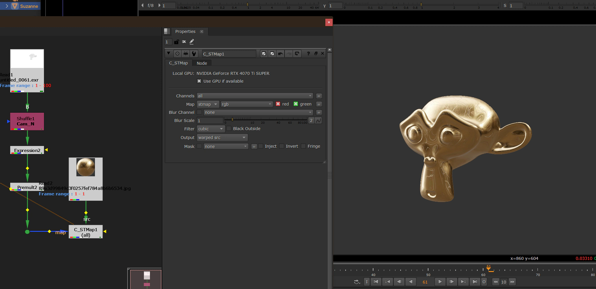
MatCap uses a prepared material-sphere image to define shading and surface appearance, as seen in Blender and ZBrush. Switching the MatCap image quickly changes the apparent material. The video below demonstrates the result.
The reference describes remapping camera-space normals from -1–1 to 0–1, then using those coordinates to sample a MatCap image. The following steps implement that idea in Nuke.
In Nuke
- Extract the camera-space normal pass (Cam_Normal).
- Remap the normal components to 0–1 with Expression: enter r * 0.5 + 0.5 for R and apply the same operation to G and B, leaving Alpha unchanged. Follow this with Premult to remove invalid values outside the object. Background pixels that were 0 become 0.5 after remapping; multiplying by Alpha returns them to 0.
- Use STMap to sample the MatCap image with the processed normals. Connect the MatCap image to src and the normals to stmap, then select the two sampling channels. Switch MatCap images to preview different material looks.(C_STMap supports GPU acceleration and can be faster than STMap.)
Performance when switching MatCap images
For example, adjusting the Alpha of a bubble MatCap can produce a transparent-looking material. The result can be composited directly or processed through Keyer to make a mask. A metallic MatCap quickly provides a different look. MatCap is useful for adding surface appearance quickly.
Object dissolution
The following UE5 dissolve-effect tutorial demonstrates using Noise to control dissolution. Rather than copying the nodes, the examples below bring the underlying calculation into Nuke.
The key is to threshold Noise, then use two slightly offset masks to isolate an edge. Once that relationship is clear, choosing the nodes is straightforward.
Use step to compare Noise with an adjustable threshold and create a mask containing only 0 and 1. Changing the threshold changes the mask coverage, gradually revealing or removing the object.
An edge highlight comes from subtracting two neighboring masks: one uses the original Noise and the other uses a slightly offset version. The narrow region between them becomes the glowing-edge mask.
Basic dissolution
- Prepare Noise for the object. This example uses APMatte's 3D Noise. UVs or another method can also provide stable Noise that follows the object.
- Add a Value control to Expression and enter step(r, Value). Here, r reads the red channel of the Noise. The result is 0 when Value is less than r, and 1 when it is greater than or equal to r. Adjust Value to change the mask coverage.
- Use the result as the object's mask. Animate Value to advance the dissolve over time.
- Duplicate this branch, add 0.1 to its input Noise, and compare it with the same Value. The offset mask has a slightly smaller region of 1s. Subtract it from the original mask to isolate a narrow edge. 0.1 controls the separation between the masks; adjust it to suit the image.
- Link both Value controls to the same parameter, then use the difference mask to brighten the edge. The highlight now follows the dissolve as its progress changes.
With Glow added
Bottom-to-top dissolution
- Extract the Z component of Position. In this footage, it varies continuously along the object's height and provides the dissolve direction. With a different coordinate convention, first check which axis represents vertical motion.
- Add the previous Noise to the height value. This breaks up a perfectly straight boundary while preserving the overall upward progression.
- Feed the combined result into step(r, Value). Adjust Value and check that the mask advances from bottom to top. Use it as the object's mask, then calculate the difference mask as before to brighten the edge.
Grid-based dissolution
- Extract Position, create a Number control for grid density, and enter random(floor(r * Number), floor(b * Number)). floor quantizes the two position components into grid coordinates; random gives each cell a fixed random value, producing block-shaped Noise. Here, r and b read the two position components used for the grid; the direction depends on the channel mapping.
- Duplicate Expression and use floor(b * Number) to generate stepped height values. Sharing the same Number keeps each height layer aligned with the grid. The preview exposure is lowered in the image to make the layers visible. The actual values are integers such as 1, 2, 3 and 4, beyond the usual 0–1 display range.
Result with preview exposure adjusted Unadjusted data - Add the cell random values to the stepped heights and link both Expression nodes to the same Number. Grid density and height layers now change together.
- Apply step(r, Value) to the combined result. As Value changes, the mask advances layer by layer. Cells within one layer appear at slightly different times because of their random values.
- Use the mask on the object and calculate the offset highlight as before. Adjust Value for dissolve progress and Size for the apparent cell size. If the edges look fragmented, check the Alpha extracted with Cryptomatte and use Erode to refine the mask edges if needed.